Note: You are viewing an old revision of this page. View the current version.
Someone needs to write this section. For now, here's enough schematics to show you what's required to hook your organ to Leslie122 (or 21H, 22H, 22R, 122R, 122V, 122RV, 142, 222, 222RV, or 242).
Looking into the male connector (as if you were going to plug it into your mouth):
<pre>
   6         1
      O   O
        *
 5  o       o  2

      o   o
   4         3


  1  Signal  (from Leslie kit) [black]
  2  Ground                    [yellow]
  3  AC power                  [gray]
  4  AC power                  [blue]
  5  B+ (from Leslie)          [brown]
  6  Signal (from Leslie kit)  [red]
</pre>
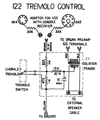
Here is a schematic of the old-style "Leslie 122 Tremolo Control Kit".

Also see the ?LeslieBox~#047357 schematics.
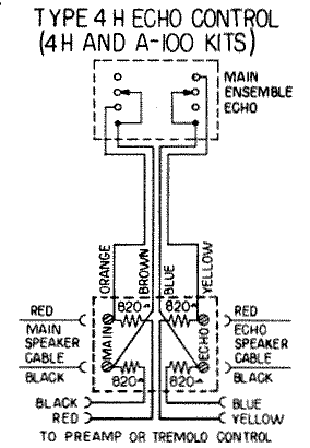
The 4H kit is used to add main-ensemble-echo switching to a console:

?FrankZueckmantel has provided  these pictures of the inside and outside of a 4H kit, as well as pictures detailing the wiring of the half-moon switches from a *4H* and a *3M* kit.
The 122 was designed nominally to connect to Hammond console organs which have balanced G-G outputs. Hammond spinets and other brands of organs do not have balanced outputs. This complicates matters somewhat.
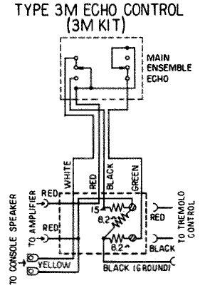
Here's the schematic of a 3M kit, which is used to hook a "122 tremolo control kit" (see above) to a spinet. If you are clever, you can figure out, from this schematic, how to hook a 122 to a spinet without the main-echo switching.

If you're having trouble following the connections in the above schematic,
you might find StefanHahn's
 colorized version
helpful.
As described above, the stock LeslieHookupKits use an isolation transformer to isolate the G-G outputs from the common-mode DC control voltage. One can, of course, use capacitors instead. BradBaker has a schematic detailing how one might do this at:
http://www.arcanedevices.com/hammond/adapter_ckt/les_sw_ckt.gif.
MikeFulk says the addition of two 0.02 uF capacitors to ground from either leg of the signal path _after_ the 10 uF NP caps is absolutely necessary to the quiet and balanced operation of the circut, and will engender its working perfectly.
There will be no perceptible degredation of the sound, says Mike Fulk.
Mike Fulk says that he has installed this system in several churches, with never a call back, nor any indication of dissatisfaction.
Possible problems with this approach include~:
 * If the two isolation capacitors are not sufficiently matched,
   the control voltage will slew at different rates on the two output
   legs resulting in (possibly loud) pops during speedswitching.

 * Mike Fulk says that matching the capacitors is unecessary, and that this, (loud pops, or any switching sound whatever), has never happened to him, as long as the .02 uF capacitors were installed.

 * Some loss of audio (voltage) level is inevitable with this type of circuit.  MikeFulk says that this is imperceptible.
(The transformers in a stock setup actually step the voltage up a tad (1:1.1?), I think.)
If you look at the circuitry provided by a "Leslie Kit," it's actually rather silly how it works. The G-G outputs on the organ preamp are fed by an internal isolation transformer (T3 on most schematics) with a grounded center tap. The kit's approach is to connect ANOTHER transformer to it, which is 1:1.1 (rather than 1:1) to compensate for the insertion loss of a second transformer. The center tap of this second transformer is used to send the leslie control voltages across the balanced line.
It's a simple matter to completely forego the second transformer and just use the first output transformer. Disconnect the center tap from ground, feed control voltages in there, and just hook the G-G outputs straight up to the Leslie. When you can hook up a Leslie with three resistors, a capacitor, and a switch, why would you pay $200 for a kit?
The only downside to this is that you can't run a Hammond tone cabinet simultaneously with this setup. There should be no detriment to the sound- it would be better if anything.
A Leslie can tell whether it should be turning fast or slow by the DC component of the audio signal being sent to it. While this does work, it's a pretty silly design. It results in pops, clicks, and some special circuitry to make it work. A better way to do this would be to send a control voltage to the Leslie on a completely separate wire.
Fortuately, you probably have one to spare. The wire that carries B+ isn't needed by most organ preamps. It can be disconnected and used to send control voltages (be careful: HammondsCanKillYou). On the Leslie side of things, you can then disconnect R4 from the audio signal and connect it to your newly freed-up wire.
Note that using this approach you don't need a hookup transformer inside the organ, and can hook the Leslie straight up to G-G.
The content of this page is Copyright (C) 2000, 2001, 2002 Geoffrey T. Dairiki and
the other authors of the content, whoever they may be.
This is free information and you are welcome redistribute it
under certain conditions; see
http://www.dairiki.org/HammondWiki/opl.html for details.
Absolutely no warrantee is made as to the correctness of
the information on this page.